3.5 KiB
Adc-Study-HardwareSoftwareInterface
Table of Content
- Adc Study, hardware software interface
- Introduction
- Hardware Software Interface
- Tests to be performed
History
| Rev | Date | Author | Description |
|---|---|---|---|
| 01 | 23/02/2025 | Ebersold A. | Creation, initial version |
Introduction
The aim of this document is to study the delta temperature measurement between the real temperature and the Condictivity board temperature measures.
Reference order
This document is referenced as 2025-02-ET-0001-Adc-Study-HardwareSoftwareInterface.md. It was created to answer nehemis request regarding poor temperature measurement results on Conductivity board. The delta between the real temparture and the measure value of the board is 2C°.
Hardware software interface
The eletronic part is depicted below. It shows the resistor devider and the
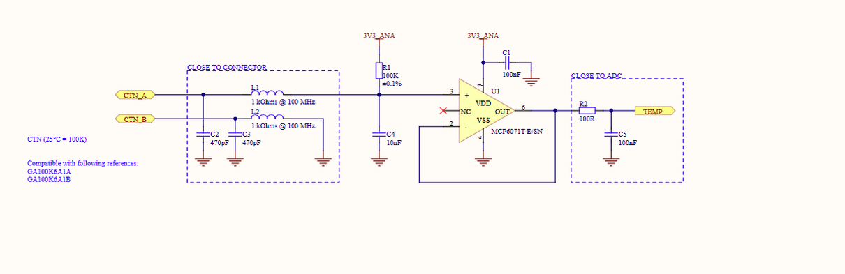
Fig 1. Electronic block
The TEMP pin is directly connected to pin PA0. Hence it must be configured as an analogue input.
ADC software configuration
As of today, the ADC is configured to perfom single acquisitions. Hight precision measurement is expected by the ADC. Hence it shall use the 12Bits resolution.
Remarque : There is a possibility to perform a tempature compensatation on VintRef value. This requires a two value aquisition for one measurement. TODO verify if this is required or not.
Data acquisition loop
Looking at the firmware, it appears that the temperature acquisition happens after each scheduler loop. A acquisition period should be defined.
Motivation: The temperature changes slowely and it's not necessary to aquire a temperature every 10ms or even lesser.
Data conversion blocks
The temperature computation goes through 3 basic blocks.
-
The raw value acquisition from the ADC
-
The conversion of the raw value into a Voltage
-
The conversion of the voltage into a resistor value
-
The conversion of the resistor into Kelvin
This block uses the Steinhard-hard method to convert the resistor value into a temperature.
-
The conversion from Kelvin to Celsius
Tests to be performed
In order to identify the root cause of the temperature measurement, I would suggest to create readable Open CAN disctionnary registers to be able to readout the ADC raw value, the computed Voltage.
For each test below, compare the voltage computed by the board with the value measure with a voltmeter at TEMP.
Values at max voltage
Connect CTN_A to 3.3V or VCC and read out the raw value and the voltage.
Values at min voltage
Connect CTN_A to ground and read out the raw value and the voltage.
Values with a known Resistor value
Connect a know resistor between CTN_A and CTN_B and read out the raw value and the voltage.